
Diaphragm walls represent one of the most important technologies of special foundation engineering. They are used for sheeting deep excavations as sheeting constructions, but at the same time they can become a permanent part of building basements in a form of construction walls.
Diaphragm walls are also used for separation of two soil environments as cut-off walls, or as a combination of the objectives listed above. Filling an excavated trench with some suitable material makes diaphragm walls - depending on the purpose this can be simple concrete, reinforced concrete, slurry or slurry with chemical additives - or a trench filled with self-hardening slurry can be set with a prefabricated element.
.jpg)
.jpg)
Monolithic diaphragm walls
Realisation of diaphragm walls starts with building of guidewalls that determine their exact position. Guide-walls stabilise the upper part of a trench under the ground, they provide support for trenching and setting of elements into a trench. In the course of excavation they serve also as a storage space for casing slurry under protection of which the diaphragm wall excavation is carried out. The casing slurry is usually made of clay and it functions as hydraulic casing of trench walls as well as it secures its stability. A diaphragm wall trench is excavated with a hydraulic or cable grab, or possibly with a hydro-cutter. The thickness of diaphragm walls ranges between 400-800 mm (in some case 1000-1200 mm), their depth does not normally exceed 30 m (in conditions of the Czech Republic), but they can be several times deeper, especially at suitable geological conditions or when a hydro-cutter is used.
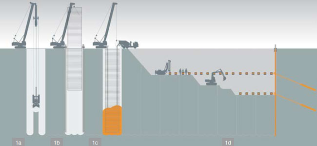
Technological process of carrying out anchored monolithic diaphragm wall
1a) Excavation of individual advances and a dike with a grab under the protection of casing slurry;
1b) Reinforcement cage and lock casings with sealing strips are gradually fitted into an excavated trench (panel);
1c) Casting of a diaphragm wall panel is carried out from below with the use of strings of concreting tremie pipes;
1d) After hardening of realised diaphragm walls it is possible to carry out their gradual excavation
and anchoring at anchoring levels to the level of the definite excavation.
A diaphragm wall is trenched on panels of mostly up to 7 m of width. Watertightness of joints between individual panels is secured with sealing strips that are threaded into steel casings forming a casing of a working joint (so called waterstop). After a panel is trenched, a projected reinforcement cage is installed into the trench filled with rejuvenated casing slurry and its casting starts with a string of concreting tremie pipes. A mixture of concrete simultaneously forces out the slurry, which is pumped out. In order to keep appropriate quality of a diaphragm wall it is necessary to ensure that casting of the whole panel is carried out as quickly as possible and without interruption (concurrent casting with the use of strings of concreting pipes set in one panel).
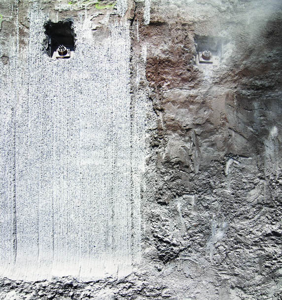
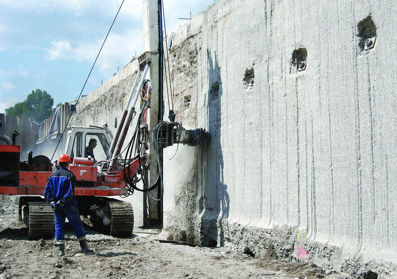
The surface of monolithic walls can subsequently be treated after they are exposed - e.g. with sprayed concretes or by cutting. Monolithic diaphragm walls can be used as construction walls in deep foundation pits, especially in cases when the bottom of a foundation pit lies under the groundwater level. They can be clamped into the subsoil, anchored with ground anchors or strutted. With the technology of monolithic diaphragm walls it is also possible to carry out foundation elements to transfer heavy loads - these are one- to three-advance panels of an I-shape, H-shape or a shape of +.
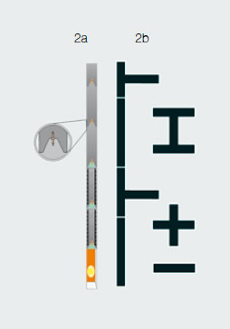 2a) Sealing of a working joint by a monolithic diaphragm wall
2b) Various ground plan shapes of diaphragm walls
.jpg)
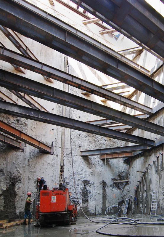
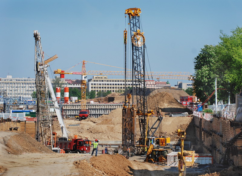
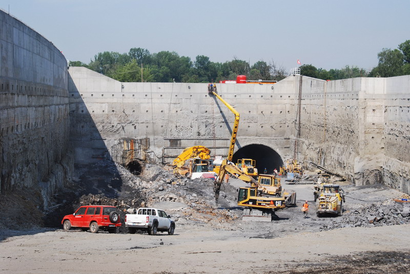
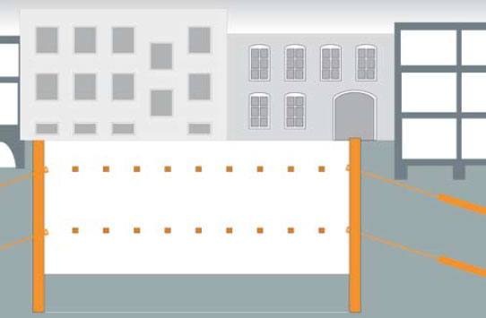
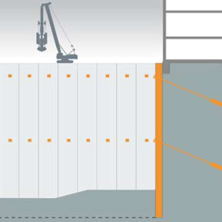
| Anchored diaphragm walls are often used when securing deep foundation pits, e.g. in built-up areas or under groundwater levels | Constructional diaphragm walls (monolithic and prefabricated) can be beneficially used when building deep tunnels or underpasses |
 | 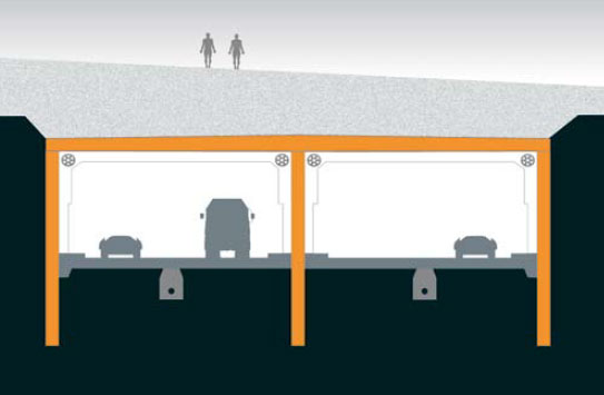 |
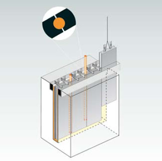
.jpg) Prefabricated diaphragm wallsThese walls are assembled from reinforced concrete panels produced to the full depth of the wall and set into a trench cased with a self-hardening slurry. The tightness of vertical joints between prefabricated elements is secured with a rubber hose inserted into a lock and grouted with stabilised cement grout. Prefabricated diaphragm walls can be anchored with ground anchors or strutted. The use of prefabricated walls is identical with standard monolithic diaphragm walls. Preferably they are applied in places where a smooth surface of their face is required, e.g. on elevational retaining walls, underpasses or in places where it is convenient to set the element above working level. If a prefabricated diaphragm wall is designed with a depth of more than 12-14 m, it will be carried out as a combined wall, where the lower part of a trench is concreted in the same way as a monolithic wall and a prefabricated element is immediately set into the fresh concrete, forming bare wall height.
Prefabricated diaphragm wallsThese walls are assembled from reinforced concrete panels produced to the full depth of the wall and set into a trench cased with a self-hardening slurry. The tightness of vertical joints between prefabricated elements is secured with a rubber hose inserted into a lock and grouted with stabilised cement grout. Prefabricated diaphragm walls can be anchored with ground anchors or strutted. The use of prefabricated walls is identical with standard monolithic diaphragm walls. Preferably they are applied in places where a smooth surface of their face is required, e.g. on elevational retaining walls, underpasses or in places where it is convenient to set the element above working level. If a prefabricated diaphragm wall is designed with a depth of more than 12-14 m, it will be carried out as a combined wall, where the lower part of a trench is concreted in the same way as a monolithic wall and a prefabricated element is immediately set into the fresh concrete, forming bare wall height.
.jpg)
.jpg)
| Anchored prefabricated diaphragm wall sheeting a foundation pit and at the same time forming an elevational surface | A scheme of gradual fitting, hanging and sealing locksof prefabricated elements into a diaphragm wall trench |
 |  |
Cut-off diaphragm walls
The realisation method is the same as with the monolithic diaphragm walls, however, instead of concrete, the trench cased with clay slurry is filled with another type of filling. It is more common to use self-hardening slurry, which has a casing function in the course of trench excavation and after hardening it becomes a proper sealing filling of the trench, therefore there is no necessity for its replacement and excavation works canbe done continuously. For a production of self-hardening slurries, composition of which is adjusted to the demands of the project, the character and level of aggressiveness of the environment, local natural materials or special sealing substances ZEOFIX™ and SEKOFIX™ developed by the Zakládání stav eb, Co. can be used. In highly aggressive environment it is possible to increase the sealing effect of a wall by using a plastic membrane inserted into the trench. Guide-walls are in cases of cut-off walls usually limited to simple templates or are left out completely. These walls are used for sealing subsoils of dams, dikes of ponds and many other works of water resources engineering. They also serve as protection screens preventing groundwater contamination and endangering the environment (see chapter Environment - soil and water protection).
Thin cut-off walls
Thin cut-off walls are successfully used for isolating two soil environments. They prevent propagation of contaminated water, for example from municipal waste landfills, and decrease hydraulic gradient of flowing groundwater, thus helping to reduce subsoil load of dams on watercourses during floods. Thin cut-off walls are made in the following way: a steel profile of I-shape or H-shape, around 60 cm of height, fitted with jets and a strong web is vibrated into the soil at a projected depth. In the course of its pulling out the created space is subsequently filled through the jets with a sealing grout, most commonly clay-cement slurry. Overlapping of vibrated profiles ensures the wall fixity; the vibrated profile width and ranges between 100 to 150 mm determine the thickness.

